Dies ist eine alte Version des Dokuments!
Swissnox S-Watt
opening
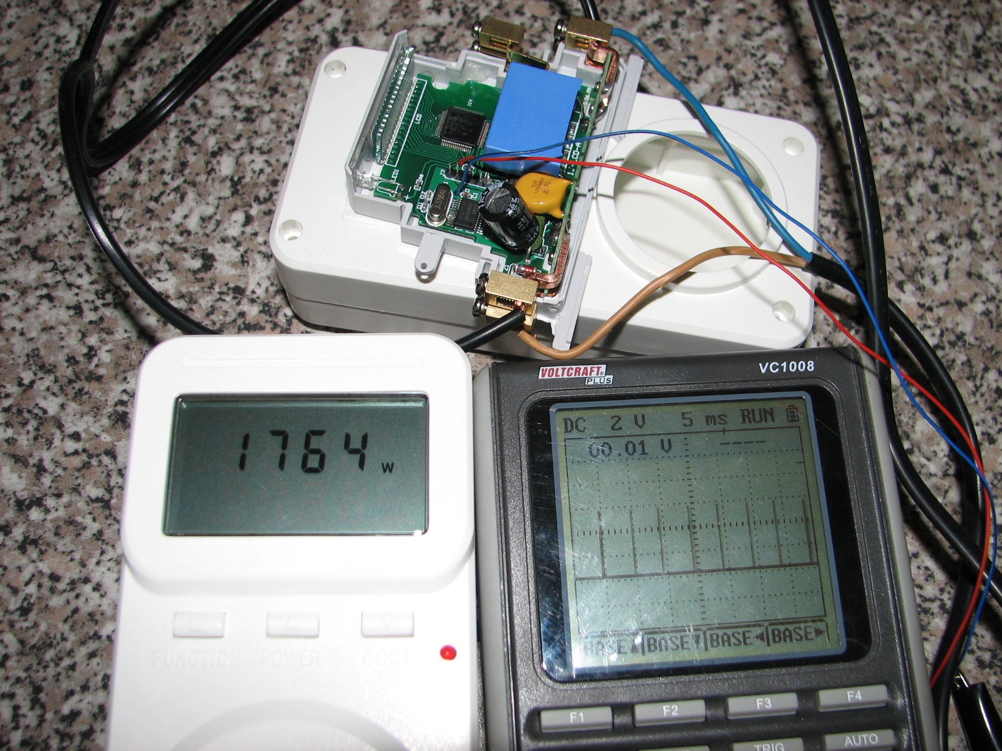
the two halves of the case are held together by the (snapped on) covers at the terminals, and slighty glued at the bottom. jam a large scredriver in between the case and covers from the bottom (remove the rail clip first, also using a little violence), and pry them off (in some of my devices some glue got in there too, tough luck). then gently pry apart the side covers from the display side, until the glue breaks.
Energy Metering IC
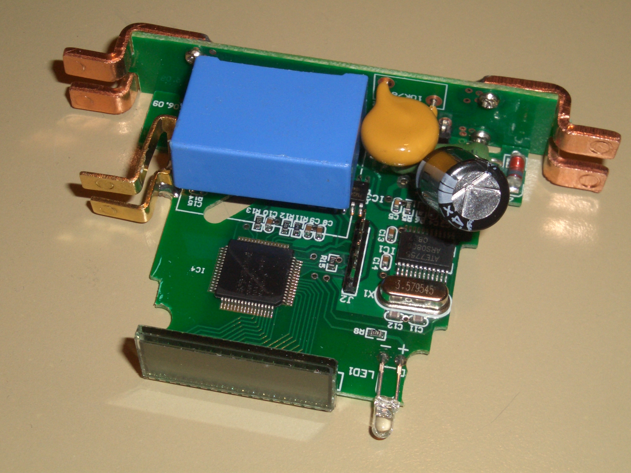
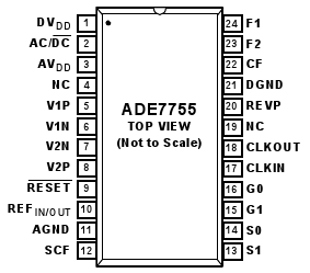
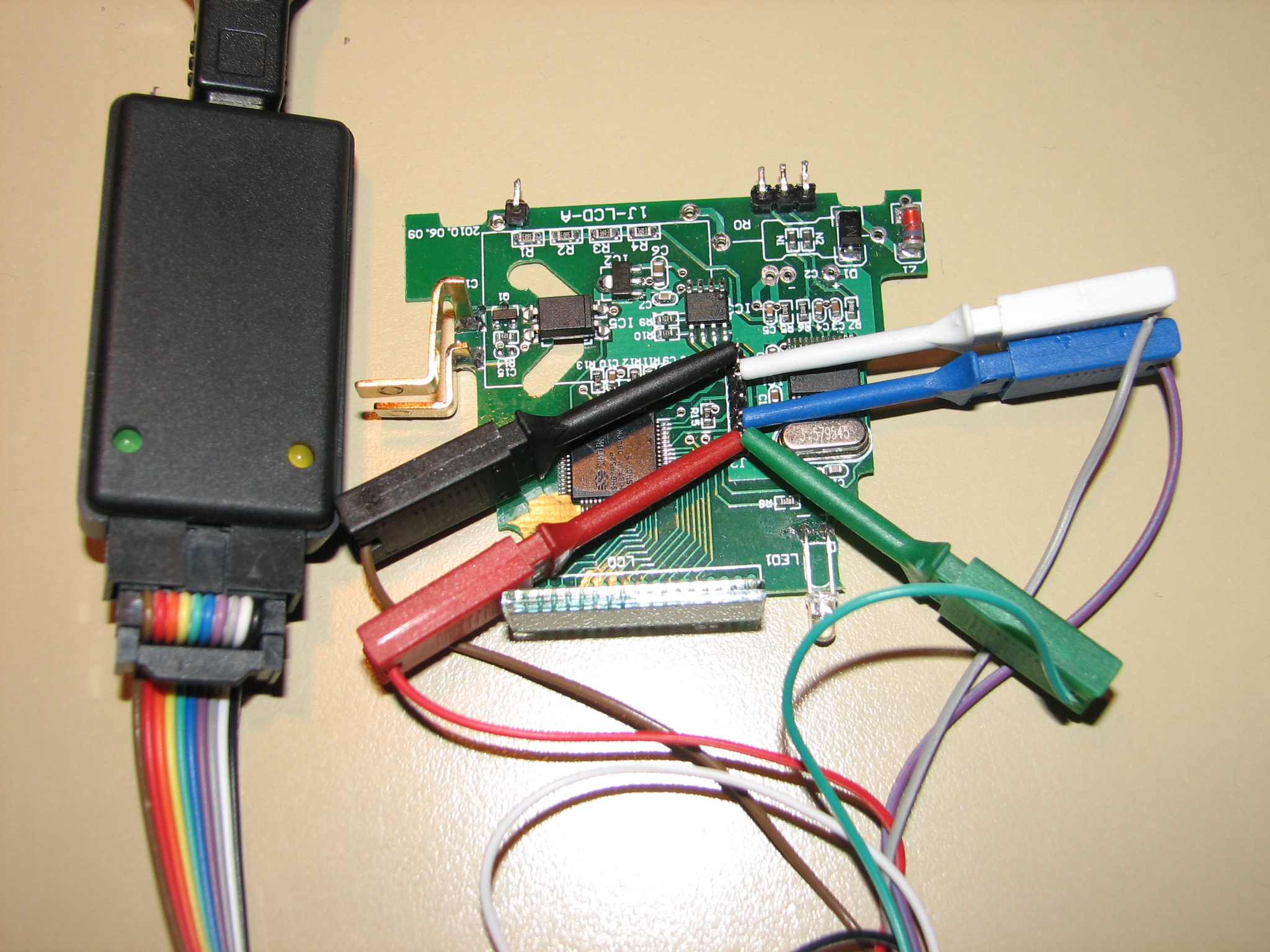
chip is labeled „ate7755“, but google turns up nothing for that. it appears that it's a clone of the analog devices ADE7755. all pins i checked so far match the ade7755 pinout.
„Energy Metering IC with Pulse Output“ – http://www.analog.com/static/imported-files/data_sheets/ADE7755.pdf
curiously, the only connection between the ATE7755 and the controller is the 7755's „CF“ pin, which is, according to the datasheet:
Calibration Frequency Logic Output. The CF logic output gives instantaneous active power information.
This output is intended to be used for calibration purposes. Also, see the SCF pin description.
the normal pulse output pins (F1 and F2) are not connected. the output signal to the optocoupler is generated by the controller.
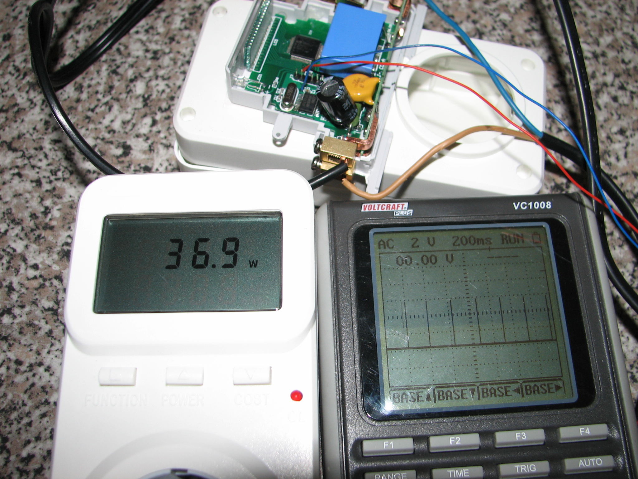
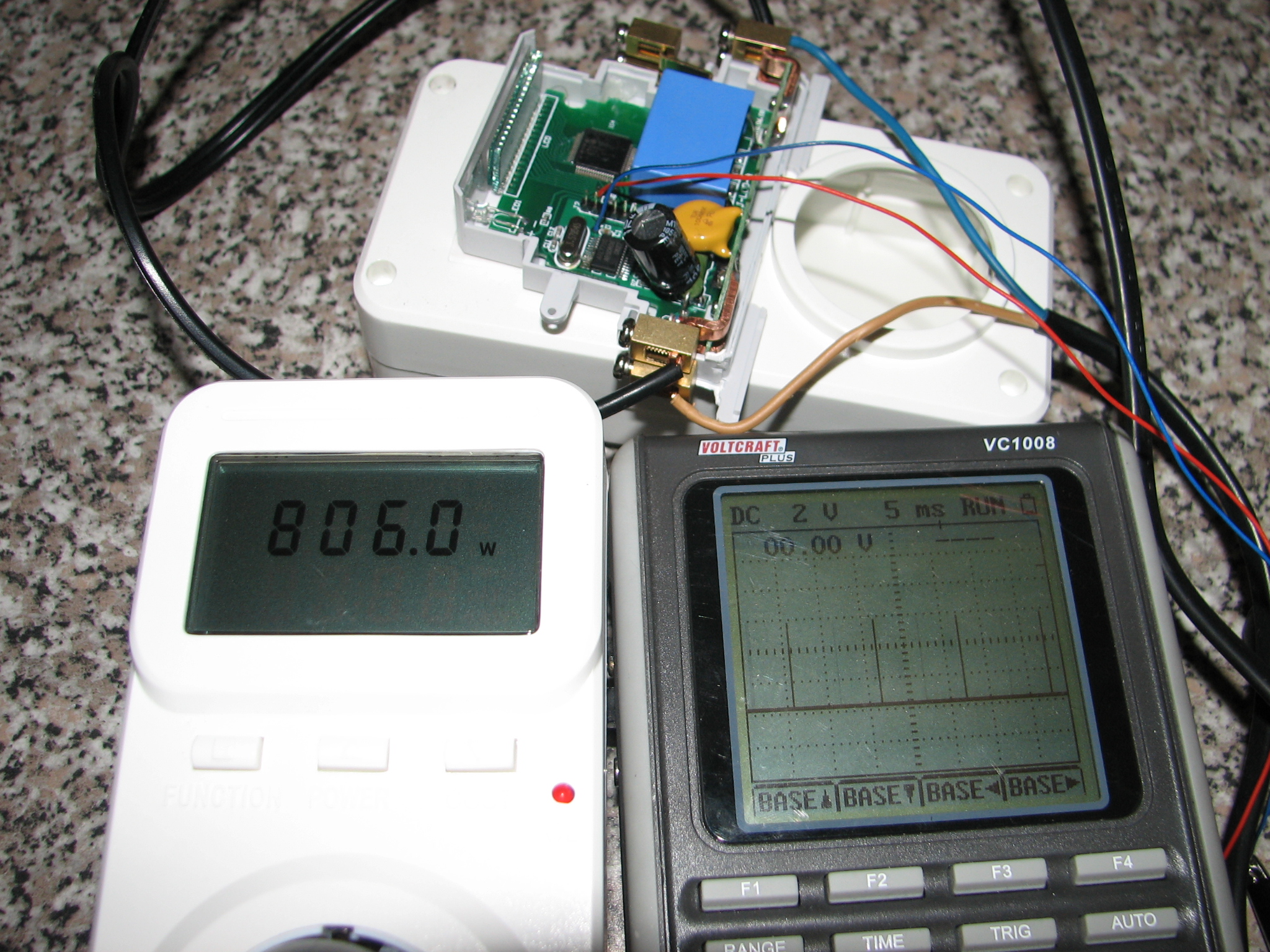
some measurements of the signal (kd302 used as reference):
| power (approx.) | pulse distance (approx.) |
| 37w | 220ms |
| 800w | 11ms |
| 1760w | 5ms |
that just leaves the question of how calibration is handled…
controller
- 4-bit OTP controller: http://www.google.com/search?q=sh67p53p
eeprom
I2C>W
Power supplies ON
I2C>P
Pull-up resistors ON
I2C>[0b10100000 0 0]
I2C START BIT
WRITE: 0xA0 ACK
WRITE: 0x00 ACK
WRITE: 0x00 ACK
I2C STOP BIT
I2C>[0b10100001 r:256]
I2C START BIT
WRITE: 0xA1 ACK
READ: ...
(when the large capacitor(?) is connected, the board can't be powered from the bus pirate, because it assumes there's a short. (the board in the picture has the large power supply components removed for taking pictures of the pcb.)
this is from a device that's still at 0.00kWh:
00: 0x00 0xFF 0x00 0xCF 0xFF 0xFF 0xFF 0xFF
08: 0xFF 0xFF 0xFF 0xFF 0xFF 0xFF 0xFF 0x00
[all 0xFF]
78: 0xFF 0xFF 0xFF 0xFF 0xFF 0xFF 0x10 0xFF
[all 0xFF]
E8: 0xFF 0xFF 0xFF 0xFF 0xFF 0x55 0xFF 0xFF
[all 0xFF]
F8: 0xFF 0xFF 0xFF 0xFF 0xFF 0xFF 0xFF 0x00
this is the device used for the CF measurements above, counter at 0.07kWh:
00: 0x00 0xFF 0x00 0xCD 0xFF 0xFF 0xFF 0xFF
08: 0xFF 0xFF 0xFF 0xFF 0xFF 0xFF 0xFF 0x07
[all 0xFF]
78: 0xFF 0xFF 0xFF 0xFF 0xFF 0xFF 0x10 0xFF
[all 0xFF]
E8: 0xFF 0xFF 0xFF 0xFF 0xFF 0x55 0xFF 0xFF
[all 0xFF]
F8: 0xFF 0xFF 0xFF 0xFF 0xFF 0xFF 0xFF 0x00
so the second line must be the counter value, with unused places left at 0xFF.
the first line (only difference between the two) must be the calibration value?
connectors
J2
power, calibration, programming(?)
| 1 (at „J2“ label) | +5V |
| 2 | i2c SCL (eeprom) |
| 3 | to controller (with pull-down resistor) |
| 4 | to controller |
| 5 | i2c SDA (eeprom) |
| 6 | GND |
